

Car Chassis Basics and How-To Design Tips
The chassis (or frame) is a structure which locates and mounts all other parts of the vehicle. It also provides a protected space for the occupant(s).
Chassis Types
There are multiple types of chassis but all of them can be classified into one of two approaches:
- Use lengths of round or square tubing, or other structural metal shapes to form the chassis structure (Space frame, multi-tube, ladder frame)
- Use joined panels to form the chassis structure (Monocoque, Unibody)
Both approaches can provide a structure capable of mounting other vehicle components, but each has its own advantages and disadvantages.
Spaceframe Chassis
The Spaceframe chassis uses numerous cut and shaped pieces of structural metal tubing (usually steel) joined together to form a strong framework. The diagram SF1 below from Ron Champion’s book “Build Your Own Sports Car For As Little As £250”, shows an example of a space frame chassis.
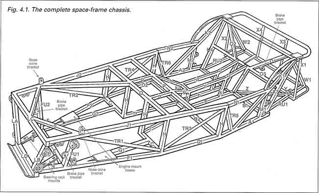
Diagram SF1. Spaceframe chassis for a “Lowcost” car. From Ron Champion’s book “Build Your Own Sports Car for as Little as £250 and Race It!”,
The principle of spaceframe design is to use triangulation of the tubes to create a rigid structure. Diagrams SF2 and SF3 below show how triangulation is used to rigidize a structure:
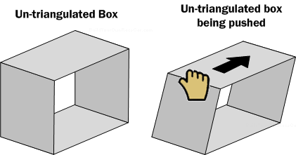
Diagram SF2. An untriangulated box (One missing its sides) is easily warped.
An un-triangulated box has very little strength. You can see this in action above. As the hand pushes against the corner of the box, the shape warps into a parallelogram.
Now, if we cross-brace or triangulate the box with a tube, the strength is greatly increased:
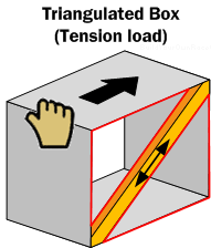
Diagram SF3. A box with a cross-member forms two triangles (Shown in red) and is said to be triangulated. The force applied to the box is trying to pull the cross-member apart.
In diagram SF3 above, the tube is being pulled in tension as if the corners of the box to where it is attached were trying to tear it apart. Because of the tube’s strength in tension, the box will not deform into the parallelogram of diagram SF2
Triangulation can also work with tubes in compression. However the ideal design always has the member tubes working in tension which provides far superior strength to tubes working in compression.
Diagram SF4 below shows how the load being applied is now attempting to crush or compress the tube instead of tearing it apart. Because of the reduced strength in compression, buckling can become an issue.
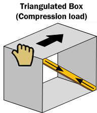
Diagram SF4. A triangulated box. The force applied to the box compresses the cross-member, potentially buckling it if the force is sufficient..
Returning to diagram SF1, there are numerous examples in this diagram of how open box tube structures have been triangulated to create a much more rigid chassis. The diagram also shows suspension and other mounting brackets.
Spaceframes usually use square or round tubing. Square tube is easier to work with because cutting it involves straight cuts at a particular angle. Round tubing does not butt up against other round tubes well, and therefore requires a special tube notcher to cut round shapes into it.
The key aspect of spaceframe design is to identify and analyze the loads that are to be expected, and design the frame and triangulation to handle those loads in an optimized fashion. As tubing in tension provides higher strength than compression, a lighter gauge tubing may be used in tension loaded areas to save weight. In areas where tubing sees compression loads, a heavier gauge or larger diameter tubing may be better to use.
Monocoque Chassis
The monocoque chassis is technically an improvement over the spaceframe chassis. Diagram MC1 below shows a simple example of the difference between spaceframe and monocoque design.
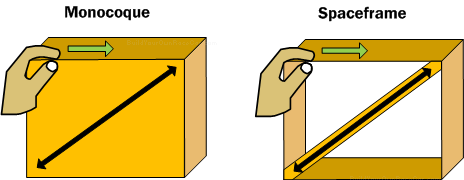
Diagram MC1. Comparing the behavior of a monocoque versus a spaceframe under tension load.
The monocoque “Box” on the left uses a panel of material to structurally “complete” the box. When the hand pushes against it in the direction shown by the green arrow, it creates a shear force across the panel. This force is effectively handled the same way a tension load is by the spaceframe triangulated box on the right. However, if the hand were to push from the other side of the box, the spaceframe tube could potentially collapse in compression, whereas the monocoque box would behave the same way it did before. See diagram MC2 below:
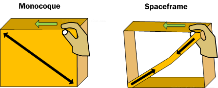
Diagram MC2. Comparing the behavior of a monocoque versus a spaceframe under compression load. Note the superior tension load handling of the monocoque and inferior compression load handling of the spaceframe.
Both types of chassis can be made just as strong as each other. However, to make an equivalent strength spaceframe generally requires more material and therefore more weight. The materials used make a big difference as well.
In diagram MC3 below, both the monocoque “box” on the left and the fully triangulated spaceframe “box” on the right would handle loads in the same manner (We’ve left out the rear of the spaceframe “box” to avoid visually complicating the diagram)
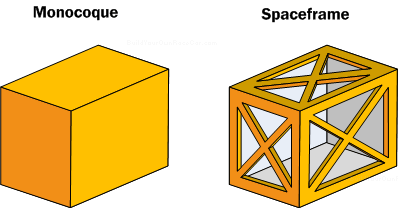
Diagram MC3. Monocoque box and “equivalent” triangulated spaceframe. (Rear of spaceframe not shown to keep diagram clarity.)
Although the monocoque can usually be made lighter and stronger than a spaceframe, it does have some downsides that make it more complicated to design, build and operate.
First, the monocoque requires the structure formed by the panels to be “complete”. If you observe the “box” in diagram MC3 that we used to demonstrate the monocoque, imagine one side of it is missing as shown in diagram MC4 below:
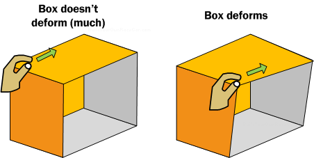
Diagram MC4. Incomplete load handling by a monocoque will cause it to deform and buckle.
We can push on the corner of the box where three panels meet (shown on the left) and it won’t warp (much), but push on a corner next to where the missing side should be and the box will buckle (as shown on the right). Where an opening exists, the chassis must handle loads through a supporting sub-structure.
A primary goal in monocoque design is to ensure that there are no unhandled load paths that can cause the monocoque structure to buckle. A buckled monocoque is no better than a buckled spaceframe tube.
In the case of poorly handled load paths, the spaceframe can be more forgiving as the tubing diameter and steel material usually provide a more gradual failure than a monocoque. However, it is better to design the chassis correctly in the first place then to rely upon noticing gradual failures.
This brings us to another key point about the monocoque—If it is damaged, it is difficult to repair compared to spaceframe tubes. It is also difficult to detect damage on a monocoque whereas bent or broken tubing is quite easy to spot.
Torsional Rigidity
Torsional rigidity is a property of every vehicle chassis that determines how much twist the chassis will experience when loads are applied through the wheels and suspension. Diagram TR1 below shows the principle.
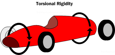
Diagram TR1. Torsional Rigidity. The less the chassis twists, the more torsionally rigid it is considered.
A chassis that has a lot of twist won’t handle as predictably as one which has very little because by twisting, the chassis begins to act like an extension of the suspension. The suspension is designed to allow the wheels/tires to follow the road’s bumps and dips. If the chassis twists when a tire hits a bump, it acts like part of the suspension, meaning that tuning the suspension is difficult or impossible. Ideally, the chassis should be ultra-rigid, and the suspension compliant.
Torsional rigidity is measured in lbs-ft/degree or kg-m/degree. One end of the chassis (front or rear) is held stationary and the other end is balanced on a point and twist is applied via a beam. Diagram TR2 below shows the basic idea:
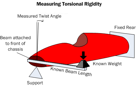
Diagram TR2. Method to measure torsional rigidity.
Chassis Design Tips (1/2)
Modifying Production Chassis
When considering modifying a production-based chassis to mount alternate suspension, engines or drivetrain, spend time studying the unibody (newer vehicle) or ladder-frame (older vehicle) structures. The structures formed by the manufacturer’s chassis designers have strong areas intended for loads and weak areas not intended to carry loads. Identifying the correct parts of the chassis structure to cut or modify is critical.
Consider using scale models of the vehicle (if plastic models were made), to mockup the changes, or 3D modeling software to do the same. If the changes involve the suspension, such as lowering the vehicle, model the new suspension first. Sometimes lowering the vehicle while using the same suspension pickup points will create poor handling.
Build Chassis Models
Modeling a spaceframe chassis with balsa wood sticks enables you to see firsthand the differences triangulation makes to the stiffness of a chassis. Herb Adams, in his book “Chassis Engineering” provides a whole chapter on chassis modeling using balsa and paper. His recommendation is for a 1/12 scale model.
Likewise, using cardboard, paper and glue to build model monocoques can be a very rewarding and low cost learning experience as well. The great thing about these materials is that they don’t have a lot of strength and so the deformations that loads create can be easily seen when loads are applied.
Design the chassis after the suspension
It is much easier to design a tentative suspension according to the rules and good geometry, and then build the chassis to conform to suspension mounting points and springs/damper mounts. See our “Designing Your Own Race Car” section
Consider the load paths
A chassis is not about “absorbing” energy, but rather about support. When considering placement of tubes, visualize the “load paths”, and consider using FEA (Finite Element Analysis software) to help analyze load scenarios. Load paths are defined as the forces resulting from accelerating and decelerating, in the longitudinal and lateral directions which follow the tubing from member to member. The first forces which come to mind are suspension mounts, but things like the battery and driver place stresses on the spaceframe structure.
Maximize CG placement and vehicle balance
Center of gravity affects the car like a pendulum. The ideal place for the CG is absolutely between the front and rear wheels and the left and right wheels. Placing the CG fore or aft or left or right of this point means that weight transfers unevenly depending on which way the car is turning, and whether it is accelerating or decelerating. The further from this ideal point, the more one end of the car acts like a pendulum, and the more difficult it is to optimize handling.
The CG is also height dependant. Placing an engine higher off the ground raises the CG, and forces larger amounts of weight to transfer when cornering, accelerating, or decelerating. The goal of vehicle design is to keep all four wheels planted if possible to maximize grip, so placing all parts in the car at their lowest possible location will help lower the CG height.
44 1 24 2