

Car Suspension Basics, How-To & Design Tips
The suspension on a vehicle serves multiple purposes:
- It provides a stable platform from which to control the vehicle
- It provides a way to isolate the chassis and driver from the shocking jolts that the tires experience going over anything but a glass-smooth surface.
- It provides a way to keep all the vehicle’s tires in contact with an uneven surface.
- It provides damping of oscillations that rubber tires, springs and uneven surfaces naturally create.
Many versions of suspension have been created over time to resolve deficiencies, but in general they all seek to control the movement of the tires in three ways:
- Laterally – Controlling side-to-side movement
- Longitudinally – Controlling forward/backward movement
- Vertically – Controlling up and down movement
Suspensions accomplish this using links and structures that locate the wheels/tires in a specific “geometry” relative to the vehicle. The geometry dictates the behavior the tires/wheel and chassis exhibit when accelerating, braking and turning.
Suspension Components
Let’s have a look at the components that make up a suspension.
Tires
As the first point of contact with the road, the tires work in conjunction with the suspension geometry and weight transfer dynamics to provide grip. Many different types of tires exist, but every tire relies upon its contact patch with the road (Shown in diagram T1 below) to create the friction needed. Generally, the larger the contact patch, the larger the amount of friction created.
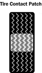
Diagram T1. Tire contact patch which contacts the road surface
The grip provided by a tire is also based on the coefficient of friction (Cf) of the rubber compound and the tire’s construction (Radial/bias). This coefficient indicates the lateral grip the tire is capable of providing for a given weight being placed on it. A Cf of 1.0 means it is capable of providing 1 lb of lateral grip for 1 lb of vertical load on it.
Racing slicks (tires with no tread) are very high Cf tires, in the range of 1.0 or more. Street (treaded) radials, on the other hand, rarely even approach a 1.0 Cf. If you were to place 500 lbs weight onto a tire with a Cf of 1.0, you could expect 500 lbs (actually a little less) of lateral grip. Without aerodynamic aids to add to apply further weight to the tire, the vehicle could almost achieve a 1G turn.
Wheels
The wheel is what the tire mounts on and each type of wheel has its own particular characteristics depending on its width, diameter and construction materials.
The primary types of wheels used on cars are alloy and steel.
Alloy wheels can be constructed to very minimal weights, as alloying materials such as aluminum and magnesium can be used. They are also generally much more expensive than their steel counterparts, but they also lack the dent resistance of steel wheels. An alloy wheel, when struck by a curb will sometimes shatter and crack. Nonetheless, for most motorsports series and street vehicles, alloys are the choice.
Steel wheels can also be constructed to very low weights and their cost is quite a bit less than the alloys, due mostly to lower cost construction. Steel wheels are deformable when struck, and will usually allow air to leak out of the tire, as opposed to shattering. NASCAR and the general stock car scene use steel wheels due to the extreme forces encountered.
Wheels, aside from their width and diameter, have an important design characteristic called “Offset”.
In the wheel/tire cutaway diagram WH1 below, the sample wheel shows a red line that represents the mounting face for the wheel—the face with the lug holes that we bolt onto the hub of the vehicle.
The yellow dotted line represents centerline of the wheel and “Zero offset” from the centerline. If we move the mounting face toward the vehicle, as show on the left in the diagram, we create “Negative Offset”. If we move the mounting face away from the vehicle, as shown on the right in the diagram, we would create “Positive Offset”
Offset is important in relation to the design of the upright/knuckle, as it determines scrub radius (see more info below).
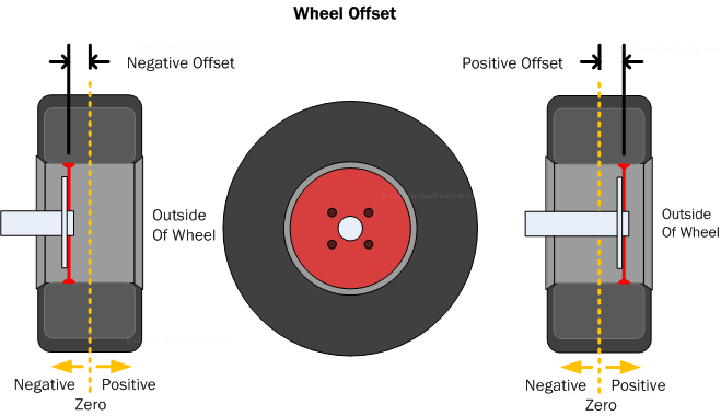
Diagram WH1. Wheel offset is the distance, positive or negative from the wheel center line when viewed from the front.
Brakes
It goes without saying that while the gas pedal on your car is the preferred pedal to push, the brakes are of vital importance as well.
Two types of brakes are available—Disc and drum. Both types use friction to turn the kinetic energy of the moving vehicle into heat. What makes one type of brake better than the other is the effectiveness of each type in dissipating or shedding the heat generated. Too much heat and the brake pad/shoe material will generate less friction, leading to what is termed “Brake fade”.
The disc brake, shown in diagram B1 below, produces more reliable stopping power under racing or hard-driving conditions because its rotor (the surface against which the brake pad generates friction and heat) is exposed to the air flow. This dissipates heat to the open air quickly.
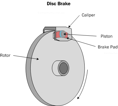
Diagram B1. Disc brake
A disc brake system works as shown in figure B2 below. The driver presses the brake pedal, which forces a piston in the master cylinder to compress the brake fluid (Yellow). The fluid runs inside a brake line to the caliper (Green) where two pistons (Blue) with attached brake pads (Red) are forced against the spinning brake rotor (Grey), generating friction and slowing the brake rotor and its attached wheel.
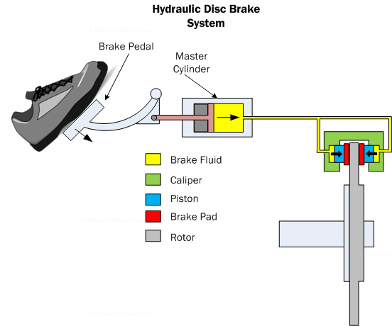
Diagram B2. Hydraulic disc brake system showing a cross-section of the master cylinder and caliper.
The drum brake, shown in figure B3 below, utilizes semi-circular shoes that are forced against the inside of the brake drum by a slave cylinder.
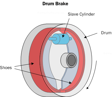
Diagram B3. Drum brake
With the brakes released, there is a small air-gap space between the shoes and the drum as shown in figure B4 below.
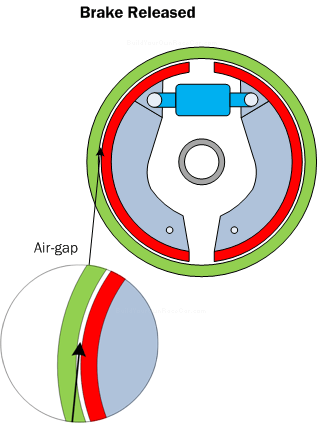
Diagram B4. The drum brake, when released, leaves an air gap between the shoes and drum.
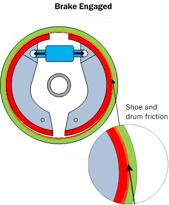
Diagram B5. The drum brake, when engaged, pushes the shoes against the drum creating the friction that turns kinetic energy into heat energy.
With the shoes engaged as shown in figure B5 above, the brake creates high levels of stopping power through large amounts of friction. However, because the drum is “closed” compared to the exposed rotor on the disc brake, more heat is retained, which leads to brake fade sooner.
Diagram B6 below shows a drum brake in a hydraulic system. The driver presses the brake pedal, which forces a piston in the master cylinder to compress the brake fluid (Yellow). The fluid runs inside a brake line to slave cylinder (Blue) which contains two pistons (Pink). These pistons are attached to the brake shoes (Red/light blue). The pistons force the brake shoes against the drum (Green), generating friction and slowing the brake drum and its attached wheel.
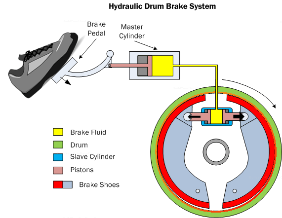
Diagram B6. Hydraulic drum brake system showing a cross-section of the master cylinder and drum assembly.
Drum brakes are cheaper to manufacture and are generally used in conjunction with a live axle. However, disc brakes are the preferred for any type of race or sports car where they can be fitted as they have less mass and better cooling.
Suspension Design Tips (1/4)
Minimize Unsprung weight
Unsprung weight, or the weight comprised by tire, wheel and suspension affects how well the tire follows the bumps and dips in the road surface. Using lighter wheels, tires, and suspension components will reduce the weight. The weight of these suspension components by itself is not so critical as the ratio between the vehicle’s sprung weight (chassis, driver, engine, etc) and the unsprung weight. The lower the unsprung weight in relation to the sprung weight, the easier it will be to control the tire/wheel via the springs, dampers (shocks) and anti-roll bars.
34 1 50 2