

Vehicle Safety Basics, How-To & Design Tips cont…
Driver/Occupant Safety cont…
Occupant Safety Cell / Roll-Bar / Anti-Intrusion
The Occupant Safety Cell, or Safety Cell for short, is located within the Impact Energy Absorption (IEA) structure. It effectively surrounds the cockpit of the car. It can be constructed as a spaceframe (tubular structure) or as a monocoque, but in either case it forms a very rigid structure which is not intended to be crushed under the most severe impacts. It is the last line of defense against external objects.
The Safety Cell is also sometimes referred to as the Survival Cell, Roll bar or Roll cage. However, the Safety Cell is usually more than just rollover protection or survival:
- It must protect the occupants from being crushed by a severe impact, even after the IEA structure has been crushed and its energy absorption capability used up.
- If possible, it must provide as much protection from different angles as possible (An issue highlighted by the open cockpits of single seater cars).
- It must provide mounting and support for the rest of the Occupant safety system components such as seats and seat belts.
- It must provide for quick escape. The design, while protective must not prevent quick extraction of injured occupants. Cars on fire or underwater present the gravest danger.
On most amateur-built race cars and scratch-built road cars, the safety cell is an integral part of the chassis, and its rigidity actually helps the overall torsional rigidity of the chassis.
In diagram OSC1 below, the Safety Cell is bolted/welded into the production-based unibody chassis. This example design uses a cross-braced roll bar combined with a side impact protecting tube structure. While it would probably provide reasonable protection at a near-stock level of racing or road use (in the case of milder impacts or rollovers), a much more substantial tubular structure cross-braced around and over the occupant(s) would likely be needed for high speed multi-car racing or high performance road driving scenarios.
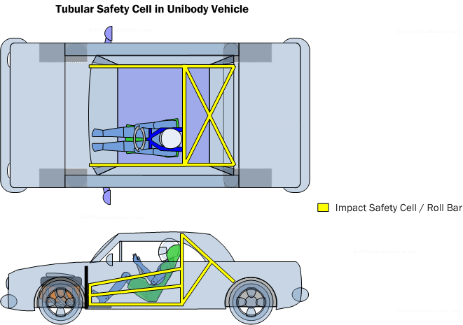
Diagram OSC1. Tubular safety cell in a unibody vehicle. Sometimes referred to as “Roll cages” they are often available from aftermarket manufacturers for a particular make/model of vehicle. Custom home-built safety cells can also be designed and fabricated to fit specific needs.
Diagram OSC2 below shows a stockcar with the tubular chassis colored to show how it behaves as both an Impact Energy Absorption (IEA) structure and as a Safety Cell. The outer tubing provides some energy absorption through its “crushability”, while the inner structure is highly triangulated to provide the Safety cell.
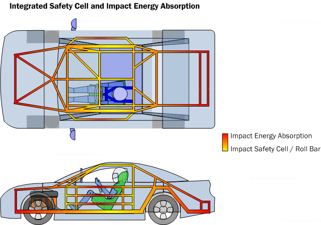
Diagram OSC2. Integrated safety cell and impact energy absorption structure. The outer structure should be designed to absorb energy. The inner structure should be designed for strength and survivability.
The Formula Car in diagram OSC3 below shows how the safety cell in many amateur cars (especially the very compact Formula cars) is actually the chassis itself. (Note: The diagram below doesn’t show the full chassis tube structure (pictured in Yellow), but only the essential safety cell portion)
One element of open cockpit cars that bears mentioning is the “Roll over protection limit”. This imaginary line drawn between the top of the roll bar and the highest safety cell point in front of the driver shows where the road will be if the safety cell is flipped upside down. When designing the safety cell, this line should pass 2-4 inches (5-10 cm) above the driver’s helmet or (in the case of road cars, their head!) to prevent their head from contacting the road surface.
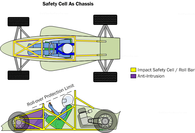
Diagram OSC3. Safety cell as chassis. In smaller scratch-built vehicles, the chassis surrounding the driver is very minimalist leading the designer to make the chassis strong enough to be the safety cell.
Anti-intrusion panels are also a consideration on tubular structured vehicles, although primarily where parts of suspension can intrude into the safety cell. On diagram OSC3 above, the anti-intrusion panels are shown in purple next to the driver’s legs. In the case of an accident where the suspension wishbones broke, they would be deflected away from the chassis by the anti-intrusion panels.
An added benefit of these panels is that they can act like monocoque panels, adding stiffness to the chassis or reducing the need for as many triangulated tubes the same area.
Seats
Racing seats are specialized to provide support to the occupants, locate the seat belts/harness and to provide some measure of protection from external objects. For High performance road cars, seats should provide a blend of good support and comfort, and if need be, use a racing harness for maximum protection
Diagram RS1 below shows an example of a racing seat.
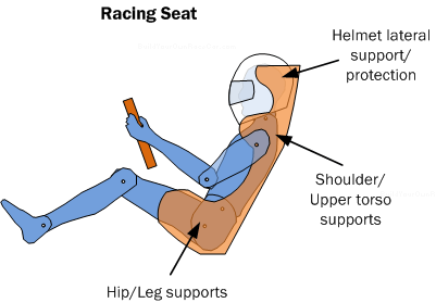
Diagram RS1. Racing seat.
The seat provides lateral support when cornering and longitudinal support when accelerating and braking. The goal of this support is to remove the requirement for the driver to “hold themselves” in place. Therefore a racing-type seat is frequently very deep to “cradle” and “hug” the driver’s body. The seat may also include head supports to limit lateral movement of the occupant’s helmet. In road cars, the seat may be shallower due to lower G-forces and to allow the occupants to get in and out easier
Racing Seat belts/harnesses are also usually threaded through special openings on the seat to locate them over the occupant’s shoulders and around their waist/crotch area. The belts themselves are attached to the chassis for maximum strength, while the seat is fastened separated to the chassis.
Racing seats generally do not have a lot of cushion like those of road cars and for good reason. The driver needs to “feel” the vehicle’s movement to maximize their control of it. If the vehicle starts to slide, and the seat has too much cushion, the feeling may be too subtle or be delayed long enough that the driver is unable to respond in time to prevent a spin.
A fine balance generally needs to be struck here, because if the seat is too soft, feeling is lost. If the seat is too hard, the driver may become sore and fatigued and possibly even bruised. Fatigue also reduces concentration, so the results can be the same as with a seat that is too soft.
Within a racing seat structure, drivers often use a molded insert that is cast using foam. Liquid foam is placed inside a plastic bag which is then placed in the seat shell. The driver sits into the seat on top of the plastic bag and the foam is then displaced around their body. Once the foam hardens, the driver has a form-fitted shell for maximum support and feel from the vehicle.
Road car seats dispense with the form-fitted foam in exchange for multi-driver flexibility and comfort.
Racing Seat Belts/Harness
Racing seat belts or harnesses, like racing seats, are specialized to provide the maximum occupant support in all racing and accident situations. In racing, the harness snugs the occupants against the seat to enhance feel. In accidents, the harness keeps the occupants from moving around the cockpit of the vehicle where they could be seriously hurt by the Safety cell or protrusions.
Harnesses come in multi-point configurations which ensure the occupants are restrained around their torso to prevent movement and to prevent them from slipping out from under the harness.
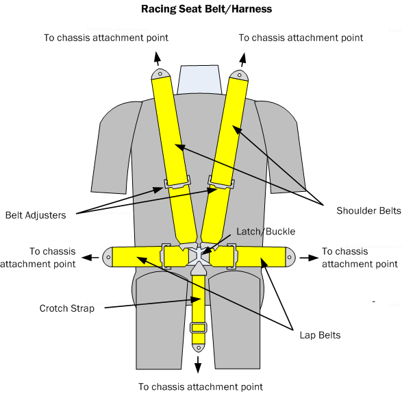
Diagram RH1. 5 point racing harness. The harness secures the driver from slipping out from under the belts and distributes impact energy across a larger portion of the torso.
The harness shown above in diagram RH1 has 5 attachment points to the chassis and 5 belts that join at a central latch or buckle. By holding the torso in an essentially cross-shaped pattern, the body cannot slip out in the case of rollovers or other sudden attitude changes. Adjusters on the belts enable them to be tightened or loosened.
Road car passengers generally like to get in and out quickly and with minimum effort, and so give up a certain amount of restraint in exchange for comfort and convenience.
Race Car HANS Device
While the HANS (Head and Neck Support) device could be considered a driver-worn device as opposed to a race vehicle component, it works in conjunction with the racing harness and therefore bears some mention. The device, as its name suggests, is intended to keep the weight of the head and helmet from causing neck injury. Based on its adoption by major racing series and track record to date, it is worth considering as part of the occupant safety system.
Safety Tips (2/3)
Triangulate the Occupant Safety Cell to prevent collapse
The occupant safety cell can be designed in such a way that a catastrophic impact which collapses the safety cell, will make the safety cell expand away from the occupants, instead of collapsing it onto the occupants. In the case of a frontal impact, this would mean the sides of the cockpit would expand outward instead of inward. By visualizing impacts from various angles (FEA software is very useful in this regard), you can determine ways to optimize the triangulation so a collapse gives the best possible result.
Use a clear windscreen or bodywork to increase vision
Using lexan or other non-shattering clear material can help increase visibility without compromising the function of the bodywork. In some cases, the driver can be lowered for better CG (center of gravity), and the normally opaque bodywork replaced with clear Lexan, to aid in re-establishing the vision field.
23 2 2