 Page: 1 2
Car Handling Basics, How-To & Design Tips cont.
Weight Transfer
All of the above characteristics come together when a vehicle starts accelerating, turning and decelerating. Each of these driving operations is asking the vehicle to change its momentum in one way or another.
By accelerating, the driver is asking the vehicle to increase its momentum in a forward direction. By decelerating, the driver is asking the vehicle to decrease its forward momentum. By turning, the driver is asking the car to change the direction of its momentum from that which it’s already headed in.
Each change is brought about by the tires in contact with the road. The tires make the change (Spinning faster, slowing down or turning) and the rest of the vehicle reacts to the change and (hopefully) assists the tires in maximizing their grip. This is where weight transfer comes in.
Acceleration Weight Transfer
To demonstrate acceleration weight transfer, let’s use the rear wheel drive car in diagram WT1 below as an example. The Center of Gravity (CG, the point where the mass of the car is centered) is always going to be above the ground. It will also always be located between the front and rear tires.
When you hit the accelerator pedal, the rear tires apply a forward acceleration. The reaction to the forward acceleration is the rearward shifting of the car’s mass (centered at the CG point) to the only point in the rear where that mass can go—the rear tire contact patch. An analogy might be the CG point “Falling” toward the rear tire contact patch. In either perspective, the shifting of the mass adds weight and traction to the rear tires.
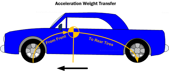
Diagram WT1. Acceleration weight transfer from front to rear wheels
In the acceleration process, the rearward shifting of the car mass also “Lifts” weight off the front wheels an equal amount. What weight the front tires lose, the rear tires gain.
Deceleration Weight Transfer
The opposite of the acceleration weight transfer takes place during deceleration. The diagram WT2 below shows the same car as diagram WT1. The CG point is in the same place, so nothing has changed except the fact that the car now has momentum and we wish to dissipate that momentum by braking.
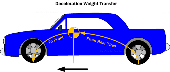
Diagram WT2. Deceleration weight transfer from rear to front wheels
When you hit the brake pedal, the four tires slow down creating a negative acceleration. The reaction to the negative acceleration is the forward shifting of the car’s mass (centered at the CG point) to the only point in the front where that mass can go—the front tire contact patch. The shifting of the mass adds weight and traction to the front tires while simultaneously “lifting” weight off the rear tires.
Turning Weight Transfer
When a car turns, the weight transfer that takes place happens both laterally (or across the car’s track width) and longitudinally (along the car’s wheelbase). For simplicity sake, we’ll focus here only on the lateral weight transfer.
Just like with acceleration and deceleration explained before, the Center of Gravity (CG, the point where the mass of the car is centered) is always going to be above the ground. It will also always be located between the left and right tires (Within the track width).
Using the top-view diagram WT3 and front-view diagram WT4 below, let’s look at how turning causes weight transfer. Let’s assume the car is moving and has forward momentum in a straight line (As shown by the black arrow in WT3). As you turn the steering wheel, the tires change angle from straight ahead to the steering angle (Shown by the yellow arrow). The car’s mass, due to the momentum will wish to keep going in a straight line, but the tires connected to it are forcing it to turn.
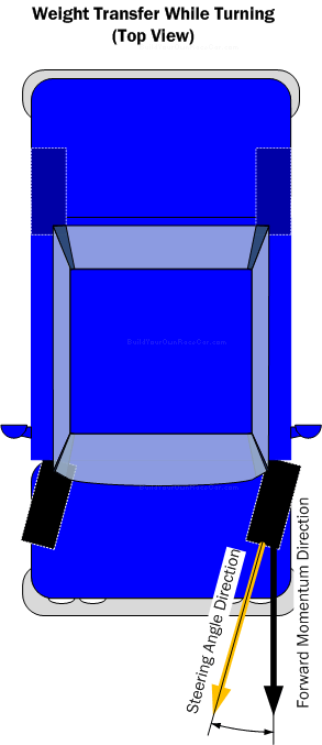
Diagram WT3. Weight transfer while turning (Top View).
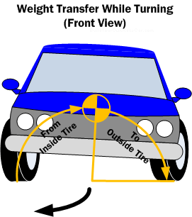
Diagram WT4. Weight transfer from inside to outside tire while turning (Front View)
As shown in diagram WT4, when the car turns, the forward momentum causes the mass of the car to shift to the only place it can go—the outside tires. The car “Rolls” onto the outside tires, adding weight and traction to those tires, while simultaneously “lifting” weight off the inside tires, reducing their traction.
Why is Weight Transfer Important?
The tires on a car generate grip because of the vertical loading on them. Generally speaking, the more weight loading we place on a tire, the greater the traction it will provide.
However, this is not entirely true because tires do not provide a linear amount of friction (traction force) compared to the vertical loading. The law of diminishing returns applies, and so as more and more weight is loaded onto a tire, the traction it provides increases at a slower rate. The imaginary tire example below in diagram WT5 shows this diminishing increase in traction.
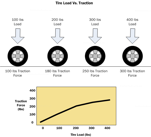
Diagram WT5. Increasing tire load versus increasing traction. The traction unfortunately does not increase at the same rate.
This becomes important because we have four tires (at least on most racing and road vehicles), and if possible, we want to have each tire produce the most grip possible. Therefore, we (usually) need to design our vehicle to transfer the minimum amount of weight from the “unloaded” tire to the “loaded” tire for maximum grip. Transfer too much weight and the useful traction provided by “unloaded” and “loaded” tires is diminished.
For example: Let’s say we’re turning a corner, and in the process the outside “loaded” tire has 400 lbs of vertical load. The inside “unloaded” tire has 100 lbs of vertical load. Using the graph above, the total traction available would be 300 lbs + 100 lbs = 400 lbs.
Now, let’s say we lowered the CG, and turn the same corner at the same speed. The outside “loaded” tire now has 300 lbs of vertical load. The inside “unloaded” tire has 200 lbs of vertical load. Using the graph, the total traction available would be 250 lbs + 180 lbs = 430 lbs.
The lowered vehicle would give better traction and turn the corner better.
Understeer/Oversteer
When a car runs out of grip at the front of the car while turning a corner, it is said to have “Understeer”. As shown in Diagram OU1 below, it is essentially turning less than it should because its front tires have reached the limit of their traction before the rear tires reach theirs.
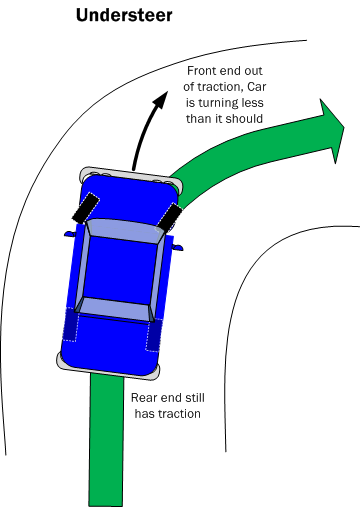
Diagram OU1. Understeering car
When a car runs out of grip at the rear of the car while turning a corner, it is said to have “Oversteer”. It is essentially turning more than it should because its rear tires have reached the limit of their traction before the front tires reach theirs.
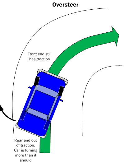
Diagram OU2. Oversteering car.
As discussed above, both these conditions are the result of how much weight is being transferred from the inside “unloaded” tires to the outside “loaded” tires. If more weight transfers and overall tire efficiency drops, overall grip at that end is reduced.
Polar Moment of Inertia
Although CG is the center of the mass of the entire vehicle, each component of the vehicle has its own mass and location as well. This is important because the further from the CG the components are, the harder it is to rotate or turn the vehicle. Each component is said to have its own polar moment of inertia.
If we use the analogy of a baseball bat, the concept becomes clearer. The longer the bat and the heavier the tips of the bat, the harder it is to swing it. It has a high polar moment of inertia. With an especially short bat that is heavy, we can still swing it in a fairly short time. It has a low polar moment of inertia. However, make the bat longer, and it takes us longer to bring our swing up to speed.
The same applies to a car. The farther away from the CG the heavy components are, the slower the vehicle will want to change direction. Looking at figure PMI1 below, we can see that the driver is close to the CG, and weighs relatively little, so their polar moment of inertia is low. The engine is heavy, but again it is still relatively close to the CG, so its polar moment of inertia is only a bit worse. The fuel tank at the back of the car is a long way from the CG, so its polar moment of inertia is high.
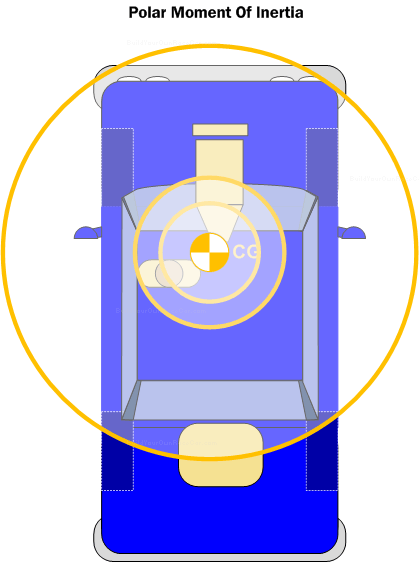
Diagram PMI1. Polar moment of intertia shown by distance of various vehicle components from the CG.
Circle of Traction
The circle of traction is a handling concept that involves how a race car or any vehicle uses the total traction available to it. If a car is braking using every bit of traction it has, it won’t have any left to turn a corner. Likewise, if a car is using every bit of traction it has to turn, it won’t be able to brake or accelerate without losing traction and sliding.
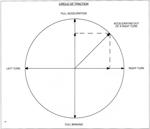
Diagram COT1. From “Chassis Engineering: Chassis Design, Building & Tuning for High Performance Handling” by Herb Adams, showing how the circle of traction works to divide traction between different accelerations.
Handling Tips (2/2)
For circle track vehicles
- Biasing the weight to the inside will reduce weight transfer to outside, increasing overall traction
- Use stagger and offset to aid turn in and weight transfer
For road course vehicles
- Having a balanced front/rear and left/right weight distribution will provide an optimal starting point for tuning the handling of a road course vehicle. If the static weight distribution is too imbalanced, more effort will be required to make the vehicle behave in a predictable manner.
Recommended Further Reading
Chassis Engineering: Chassis Design, Building & Tuning for High Performance Handling Chassis Engineering is a great introduction to race car design. In a practical and down-to-earth way, it covers the fundamentals of how race cars handle and the requirements for designing and constructing a car. The book includes chapters on chassis design, suspension design, frame construction, aerodynamics and tuning. Overall it provides the reader with the foundation of how the key components of a race car work and interact together.
 Get "Chassis Engineering: Chassis Design, Building & Tuning for High Performance Handling":


How to Make Your Car Handle Teaches how to improve vehicle handling through suspension and chassis modifications and understanding vehicle dynamics. Includes basic suspension theory on roll centers, roll axis, camber change, bump steer, anti-dive, ride rate, ride balance as well practical chassis modifications.
Get "How to Make Your Car Handle":- View all handling/vehicle dynamics books
Continue to Car Suspension Basics, How-To & Design Tips…
29 2 15 1
Page: 1 2