

Car Handling Basics, How-To & Design Tips
Introduction
“Handling” is the term used to describe the fundamental behavior of a vehicle being driven. It is often described in terms of the response a car has to driver input. For example, the car pushes (or has understeer) in a corner or the car is loose (or has oversteer) in a corner.
What is being described is the response of the vehicle from a combination of factors including how the weight is distributed in the car, how the suspension reacts to the driving forces, and how the tires contact the road surface.
By understanding the physics of handling, we can visualize the behavior of the car we are designing or working on to optimize its performance. In our guide below we touch on the various elements that make up car handling.
Weight Distribution
The positions of the components in a vehicle determine how its weight is distributed while it is standing still. This Static Weight Distribution will also affect the way it handles on the track. The tires connecting the vehicle to the track provide friction with the road surface and impart turning, braking and acceleration forces into the suspension (if any) and chassis. The Weight Transfer due to these forces largely dictates whether the vehicle handles as expected.
Track width
Track width, as shown in diagram TW1 below, is the width of the car, measured between the centers of the tire contact patches. The track width is important because it determines how much weight is transferred by the mass of the car in cornering.
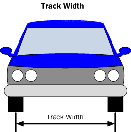
Diagram TW1. Track width is the measurement between the centerlines of the tires when viewed from the front or rear of the vehicle
Wheelbase
The wheelbase of a vehicle, as shown in diagram WB1 below, is the distance between the front and rear wheels, measured at the centers of the wheels. The wheelbase is important, because it determines the weight transferred by the mass of the car in acceleration and braking as well as the yaw characteristics in turning.
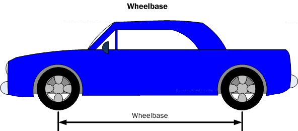
Diagram WB1. Wheelbase is a measurement of the distance between the centers of the front and rear wheels when viewed from the side.
Static Weight Distribution
Every part of a vehicle has mass and depending on where that mass is located relative to the tires, it will affect the how much weight is on each tire.
Static weight distribution is defined by two ratios:
- A ratio of the total weight on the front or rear tires of the vehicle.
- A ratio of the total weight on the left and right tires of the vehicle.
In example diagram SWD1 below, the car’s center is marked with a red cross, which lay half way along the Wheelbase, and half way along the Track Width.
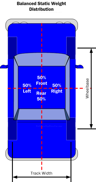
Diagram SWD1. Balanced static weight distribution where mass is divided evenly front and back and left and right
The weight is balanced evenly between the front and rear: 50% front/50% rear. The weight is also balanced evenly between the left and right sides: 50% left/50% right.
In reality, most vehicles never balance their static weight this well because large components and their necessary positions do not allow it. Given a front engine and driver, a car might look like the example in diagram SWD2 below:
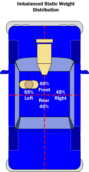
Diagram SWD2. Weight distribution biased to left and front by the driver and engine/transmission.
The driver’s weight shifts the Left/Right distribution to 55% left/45% right. The engine shifts the Front/Rear distribution to 60% front/40% rear. Notice the position of the red cross doesn’t change, but the weight percentage on each side does.
CG Location
Knowing the weight distribution, front to rear and left to right, we can pinpoint where the CG (Center of gravity is located along the length (Longitudinal) and width (Lateral) of the car. The CG indicates the point that you could balance the car on if you were to jack it up underneath that point. With the example above, the CG would be located approximately as shown in Diagram SWD3 below:
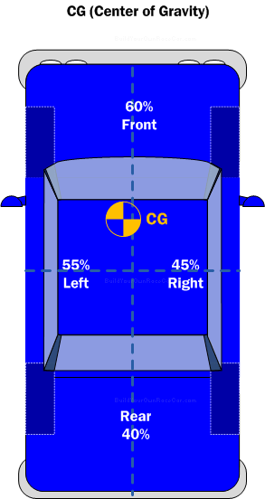
Diagram SWD3. The lateral and longitudinal Center of Gravity (CG) location
CG Height
Static weight distribution is just a 2D (Two-dimensional) concept, until we take into account the height from the ground of the same components described above. The CG height is determined by where the mass of the vehicle components are located vertically.
In example diagram CG1 below, the car on the right has been lowered, so the engine, body, driver, and all other components are lower to the ground (CG Height “Y”) than the those in the car on the left (CG Height “X”):
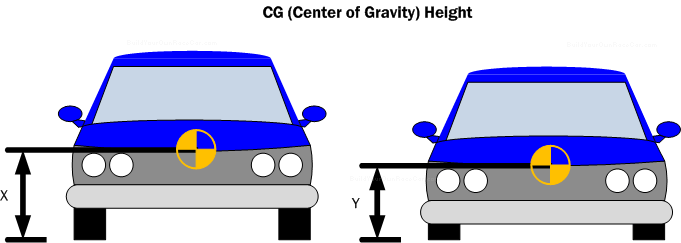
Diagram CG1. Center of Gravity (CG) height from the ground
Any vehicle that wants to turn at high speeds is usually as close to the ground as its intended road surface will allow. We’ll see why next in “Weight transfer”.
Handling Tips (1/2)
For all vehicles
- Minimize CG height
- Keep static weight distribution as balanced as possible (front/rear, and left/right). Later tuning will be easier than working with a large imbalance.
- Unless the surface is very slippery, reducing weight transfer in cornering usually gives more traction
- In cases where the surface is slippery, a higher CG or narrower track width will aid in transferring weight to outside wheels to give more “bite”. Narrower tires may also aid in this situation.
- Optimize Polar moment of inertia by packaging components as near as possible to the CG.
29 2 25 1