

Car Suspension Basics, How-To & Design Tips cont…
Suspension Components cont…
Knuckles/Uprights
The upright or knuckle attaches the wheel, brake rotor, hub, brake caliper and steering arm to the vehicle as shown in diagram KU1 below. The upright also locates these components in space.
The design of the upright or knuckle determines the geometry on the “outboard” side of the suspension. (The mount points on the chassis and wishbones/links form the “inboard” side of the suspension, and provide their own contribution to the overall geometry of the suspension.)
Diagram KU1 shows an example of an independent wishbone suspension that is not driven. The upright (Yellow) is attached to the vehicle using the upper and lower wishbones which have ball joints or rod-ends. This allows the upright to move vertically and to rotate about the king pin axis (See below).
Integrated into or attached to the upright is the spindle. Bearings (Orange) are inserted into the hub (Red) and it is slid over the spindle and held in place by a retaining nut. The brake disc (Blue) slides over the lugs (Threaded bolts) extending from the hub. The brake caliper (Light blue) is attached to the upright using a bracket.
Controlling the steering or toe angle of the upright is the steering/toe link which has a rod end that fastens to an arm (Purple) on the upright.
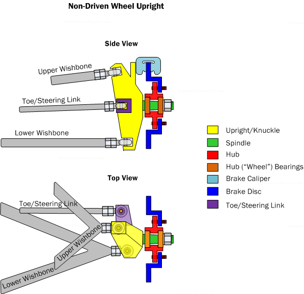
Diagram KU1. Side and top views of a non-driven upright/knuckle within an independent wishbone suspension.
Diagram KU2 shows an example of an independent wishbone suspension for a driven wheel. As with the non-driven version, the upright (Yellow) is attached to the vehicle using the upper and lower wishbones which have ball joints or rod-ends. This allows the upright to move vertically and to rotate about the king pin axis (See below).
In order to drive the wheel, a half-shaft or driveshaft (Gold) extends from the chassis and uses a CV joint to enable suspension movement while driving the wheel. A splined shaft (Green) extends from the CV joint and passes through the upright. Two bearings (Orange) are used to support the shaft inside the upright. The hub (Red) slides over the spline on the shaft and is secured using a nut.
The brake disk (Blue) then slides over the lugs extending from the hub. The brake caliper (Light blue) is attached to the upright using a bracket.
Controlling the steering or toe angle of the upright is the steering/toe link which has a rod end that fastens to an arm (Purple) on the upright.
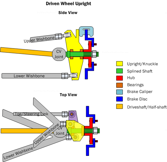
Diagram KU2. Side and top views of a driven upright/knuckle within an independent wishbone suspension and half-shaft/cv-joint combination.
Wishbones/Links
Wishbones, links and axles connect the previously mentioned upright or knuckle to the car chassis. Depending on suspension type, they behave in different ways, but always with the goals of controlling lateral, longitudinal and vertical motion of the wheels.
Wishbones look just like the name suggests. Diagram WL1 below shows a wishbone highlighted in yellow.
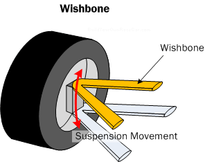
Diagram WL1. Wishbone (Also sometimes referred to as an A-Arm)
Links (sometimes called radius rods) are rods that are used to enable the wheel to move in a particular axis. Diagram WL2 below shows how a live axle uses links to control its movement. The parallel rods allow the wheels to move up and down. The lateral rod controls lateral movement of the axle.
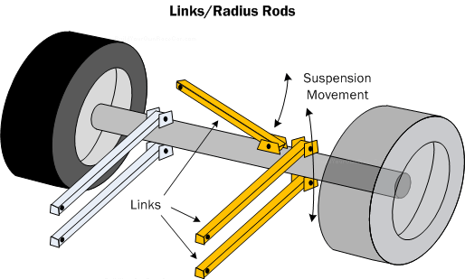
Diagram WL2. Links and Radius rods locate the axle in space and control movement.
Axles
Axles are used to connect the left and right wheels at the front or rear of the vehicle. One of the oldest ways of suspending a vehicle, the axles as shown below have been used extensively on road cars and trucks and on race cars, especially those based on production vehicles.
Diagram AX1 below shows a driven live axle. This axle is used primarily at the rear of a rear-drive vehicle. The differential accepts power through an input shaft, and transfers it through the axle shafts to the wheels. The axle shafts are housed inside of axle tubes which provide protection from the environment and the strength needed to support a vehicle chassis. The axle shafts connect to hubs at either end and these in turn mount the wheels and tires. As shown above in diagram SC2, the live axle uses links and springs/dampers to connect to the chassis.
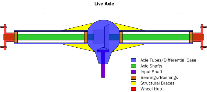
Diagram AX1. Live axle with differential.
Diagram AX2 below shows a beam axle, which can be used as a rear axle in front-wheel drive vehicles or as a front axle in rear wheel drive vehicles. It uses a simple beam that attaches to the chassis through links and springs/dampers. At the ends of the beam can be steerable knuckles/hubs (for a front axle) or non-steerable hubs (for a rear axle.). In the example AX2 below, the beam has stub axles at it ends to which hubs are mounted on bearings.
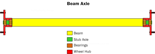
Diagram AX2. Beam axle with freely spinning hubs mounted on stub axles.
Diagram AX3 below shows a go-kart axle, which uses a one piece shaft without a differential. This is the “Simplest” of axle types, and consists of a single hollow tube or solid rod supported by bearings which are housed in supports that attach to the chassis. To the ends of the axle are affixed hubs for mounting wheels/tires. Mid-mounted on the axle is a sprocket hub to which a chain sprocket is bolted and driven by the go-kart motor.
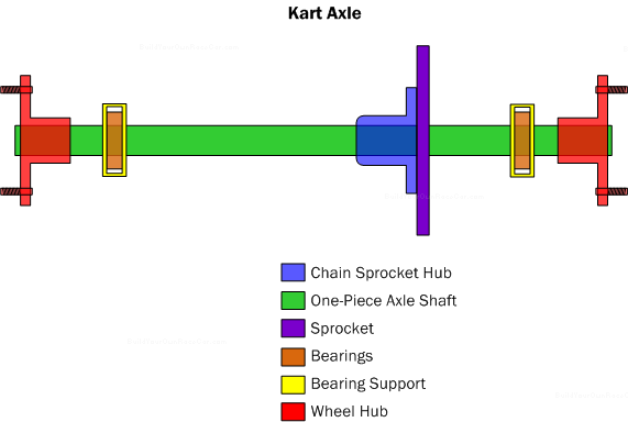
Diagram AX3. The kart axle is a single piece tube supported by bearings. A drive sprocket and wheel hubs are mounted to the axle.
Due to the single axle, the inside wheel travels at the same speed as the outside even when going around corners. This would normally have a detrimental effect on turning because the rear wheels would push at the same speed in a straight line while the front wheels are trying to turn. Go-karts get around this problem by lifting the inside rear wheel in corners using a special front suspension geometry. The inside rear wheel is spinning above the road while the kart is turning.
Suspension Design Tips (2/4)
Maximize Aerodynamics
On vehicles where the suspension is exposed and speeds are high, moving components under bodywork and streamlining those still left exposed can provide an advantage.
Use Scrub Radius For Feel
The feel of what the tires are doing in relation to the road is transmitted through the suspension, into the chassis and steering, and finally to the driver. Scrub radius helps this feel by providing feedback from the contact patch.
With a small amount of scrub radius, the tire is turned about the kingpin axis, slightly offset from the tire’s centerline. This creates a small tire/road friction resistance that in turn translates into feedback from the road. The scrub radius can enable the driver to feel when the tires lose traction, without being “too far gone” to recover.
34 1 34 2