
Car Aerodynamics Basics and How-To Design Tips cont…
Aerodynamic Devices cont…
Wings
Probably the most popular form of aerodynamic device is the wing. Wings can perform very efficiently by generating a lot of downforce for a small penalty in drag. Spoilers are not nearly as efficient, but because of their practicality they are used a lot on sedans where wings are less efficient.
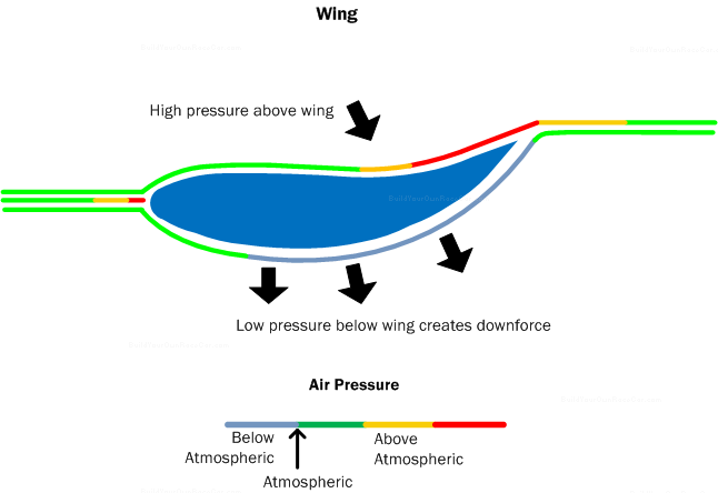
Diagram AD5. Wings generate downforce by a pressure difference between the top and bottom surfaces.
The wing, as shown in diagram AD5 above, generates downforce by using the difference in air pressure between the top and bottom surfaces. This air pressure difference results from the way the air flows around the wing shape.
According to Bernoulli’s principle, the higher the speed of a given volume of air, the lower the pressure that air will have. Therefore to create lower air pressure, we need to speed up the air flow.
A wing does this by making the air molecules travel different distances from the leading edge to the trailing edge. The longer underside of the wing requires the air flowing on that side to move at a higher speed (lower pressure) to meet up with the air flowing at a lower speed (higher pressure) over the top side of the wing.
The lower pressure area under the wing allows the higher pressure area above the wing to “push” down on the wing, and hence the vehicle it’s mounted to. The angle of attack or wing angle can be increased to enable even larger pressure differences, but eventually the wing will stall and lose downforce. Drag also increases with higher angles of attack.
Downforce can be increased even more without stalling the wing by using multi-element wings that position one or more small wings behind a larger wing. In his book “Race Car Aerodynamics: Designing for Speed“, Joseph Katz provides a Coefficient of pressure plot with an overlaid multi-element wing profile, shown in diagram AD6, below. The positioning of the elements is critical, with gaps between the wing elements “feeding” the low pressure side of the smaller wings.
NOTE: The wing in the diagram is shown “upside down” compared to how it would be mounted on a race car. The diagram is meant to plot negative pressure coefficients from the front to the rear (the Chord) of the wing (x/c)
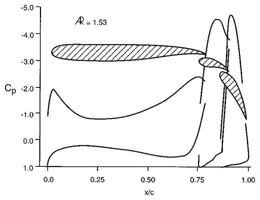
Diagram AD6. Pressure coefficients (Cp) of a multi-element wing. Diagram from Joseph Katz’s book “Race Car Aerodynamics: Designing for Speed”. Each successive element is positioned with precision to complement and harness the flow from the previous element. © Bentley Publishers
Wings can be coupled with endplates to prevent high pressure air spilling over the ends to the low pressure underside. Diagram AD7 below shows a wing with endplates:
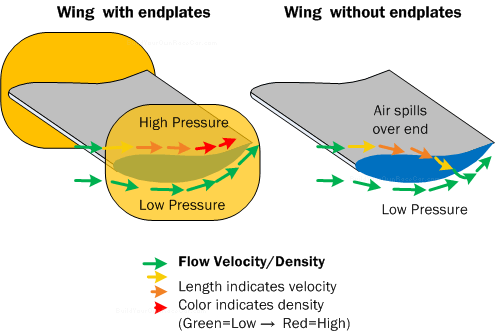
Diagram AD7. Wing endplates prevent high pressure air (on top) from migrating over the ends of the wing to the low pressure side (on bottom)
Venturi Tunnels
Venturi tunnels, much the like a venturi tube observed in a laboratory, use the constriction of a flow to generate high speed, low air pressure areas under the race car. In diagram AD8 below, we show a car with a venturi tunnel, and below that a similar venturi tube you might see in a lab.
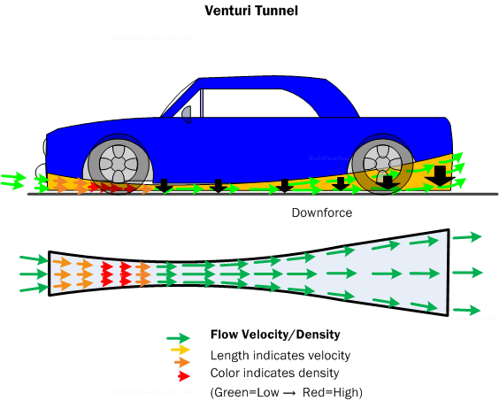
Diagram AD8. The Venturi tunnel shape increases the velocity of the mass of air flowing through it, lowering the pressure and generating downforce.
On race vehicles, the venturi is usually formed by making the undertray of the vehicle shaped like an inverted wing. The distance between the undertray and the road forms a constriction and then expands to enable the low pressure created by the constriction to act along the middle and rear and of the vehicle. Venturis are very efficient devices but are susceptible to changes in vehicle ride height.
Diffusers
A diffuser, shown in diagram AD9 below, is used to generate downforce at the rear of a vehicle. Similar to a venturi tunnel, it forms a curvature similar to the underside of a wing immediately before the low pressure area behind the vehicle. By doing so, the air flowing under the vehicle increases in speed and drops in pressure, creating downforce. Diffusers and venturi tunnels leverage the low pressure area behind the vehicle, and can sometimes leverage high speed exhaust gases ejected into the diffuser to create even lower pressure.
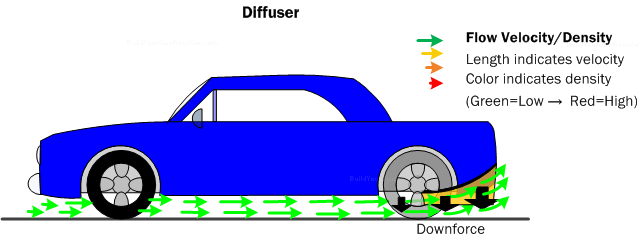
Diagram AD9. The diffuser uses the underside of the car body to mimic the underside of a wing. The diffuser’s expanding opening creates a low pressure area under the rear of the car that generates downforce.
Aerodynamics How-To Tips (4/4)
Rake the chassis
The chassis, as mentioned in the aerodynamics theory section above, is capable of being slightly lower to the ground in the front than in the rear. The lower “Nose” of the car reduces the volume of air able to pass under the car, and the higher “Tail” of the car creates an expanding space where a vacuum effect can form. This lowers the air pressure beneath the car, creating downforce.
Cover or streamline Exposed Wishbones
Exposed wishbones (on open wheel cars) are often made from circular steel tube to save cost. However, these circular tubes generate turbulence. It may be worth considering the use of oval tubing, or a tube fairing that creates an oval shape over top of the round tubing. See diagram AT1 below:
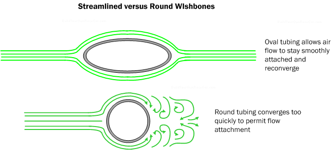
Diagram AT1. Streamlined wishbone tubing improves the smoothness of the air flow to parts of the car behind and reduces drag,
Recommended Further Reading
Race Car Aerodynamics: Designing for Speed An in-depth and comprehensive guide to race car aerodynamic theory and practice. It covers everything a designer needs to know--from basic theory and aero devices (i.e. wings, venturis, diffusers, spoilers and more) to their applications on different types of race cars. Written with the non-engineer in mind, it also provides many examples and diagrams that show how to optimize the air flow around and through a race vehicle.
Get "Race Car Aerodynamics: Designing for Speed":


Competition Car Downforce: A Practical Guide A comprehensive guide for understanding, designing and building aerodynamic devices for race cars. It includes aerodynamic theory, how devices work, design, and construction techniques. Also published in a newer version ("Competition Car Aerodynamics: A Practical Guide").
Get "Competition Car Downforce: A Practical Guide":Aerodynamics of Road Vehicles: From Fluid Mechanics to Vehicle Engineering The most comprehensive and in-depth guide to aerodynamic principles and their application to road vehicles. Passenger car, commercial vehicle, sports car, race car, and motorcycle aerodynamics are all examined in detail. Includes theory and practical applications in fuel economy, directional stability, cooling, and passenger comfort. Also discusses design, measurement, testing and computational fluid dynamics.
Get "Aerodynamics of Road Vehicles: From Fluid Mechanics to Vehicle Engineering":- View all aerodynamics books
Continue on to Car Safety Basics and How-To Tips…
49 2 32 7